
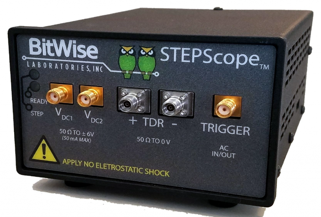
BitWise Laboratories STEPScopeTM is a compact device integrating a fast output pulser with a high-bandwidth low jitter input sampler to perform step response analysis on Reflected and Through-channel pulses for calculating Time Domain Reflectometry(TDR) and Time Domain Transmissometry(TDT) analysis.
Optional S-parameter analysis converts step response analysis into Return Loss (S11) and Insertion Loss (S21) results.
[STEPScope TDR Datasheet Download]
특징
-
- MADE IN USA(Silicon Valley)
- Compact
- 동급 최강 성능
- 동급 최저 비용
- TDR/TDT & S-PARA 측정
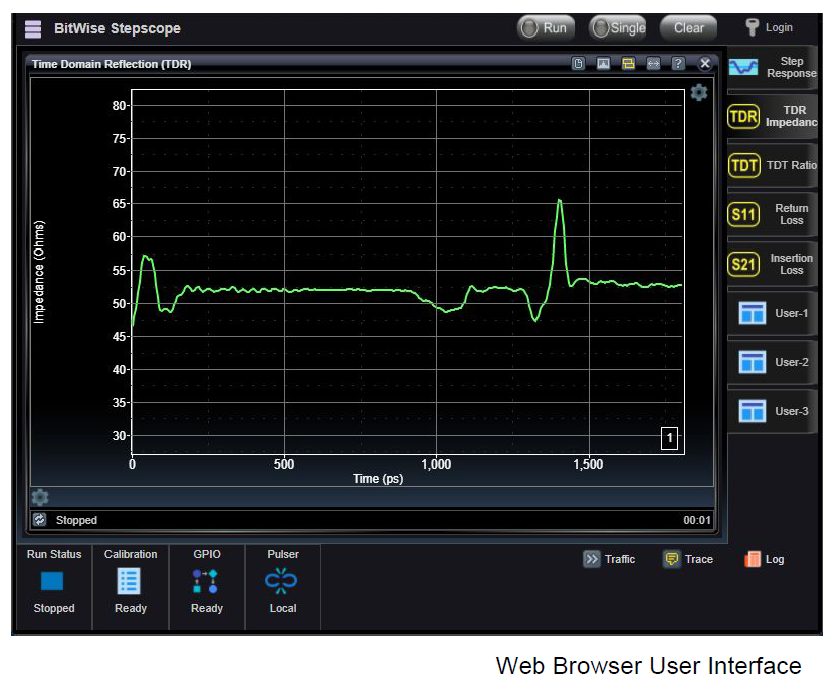
TDR results show impedance Ohms as the signal is transmitted through the channel. Impedance disruptions cause reflections that are responsible for degraded performance. STEPScopeTM settings are configured using the web browser user interface. Status Bar indicators along the bottom show the current operating status. On the right, the user can easily access other pages of the user interface.
주요사양
-
- Compact TDR/TDT Solution including Integrated Pulser and Sampler
- 20 psec Edge Rate (10/90) - 동급 최고 사양
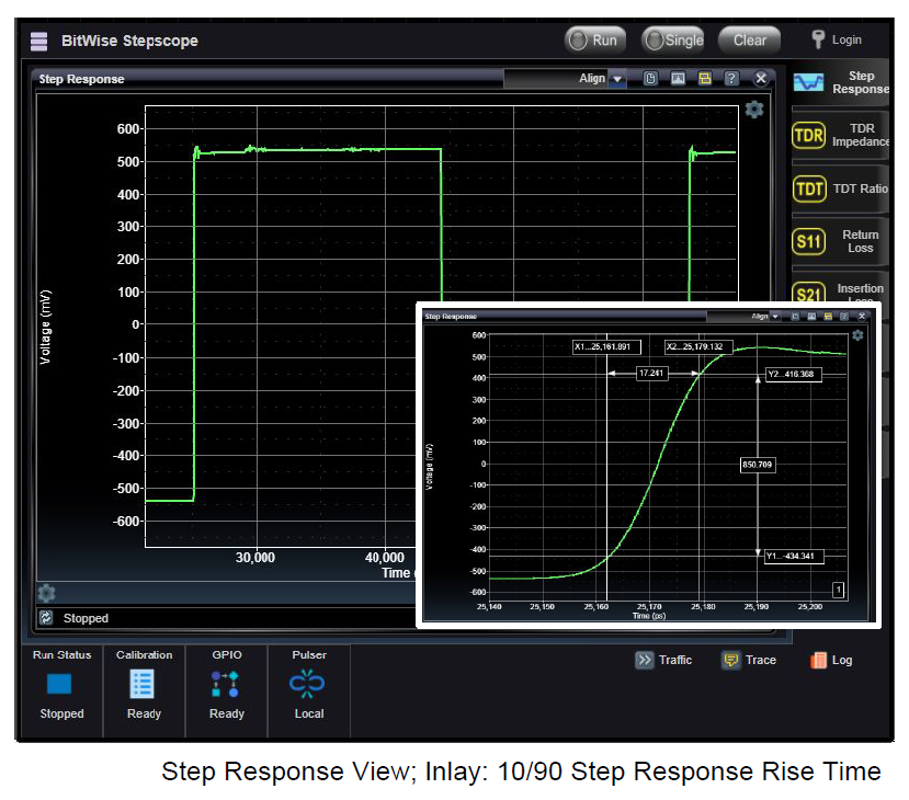
The Step Response view shows the captured Voltage vs. Time waveform acquired by the internal sampler. Panning and zooming and cursors are fully supported to allow sub-picosecond measurements. In this image, the rising edge of the Incident pulse is zoomed-in on and cursors are used to measure the 10/90 rise time. Fundamentally, it is Step Response data that is used to compute all TDR, TDT and S-parameter results.
-
- 20 GHz Bandwidth - 동급 최고 사양
- Fast Averaged Waveform Capture and Download
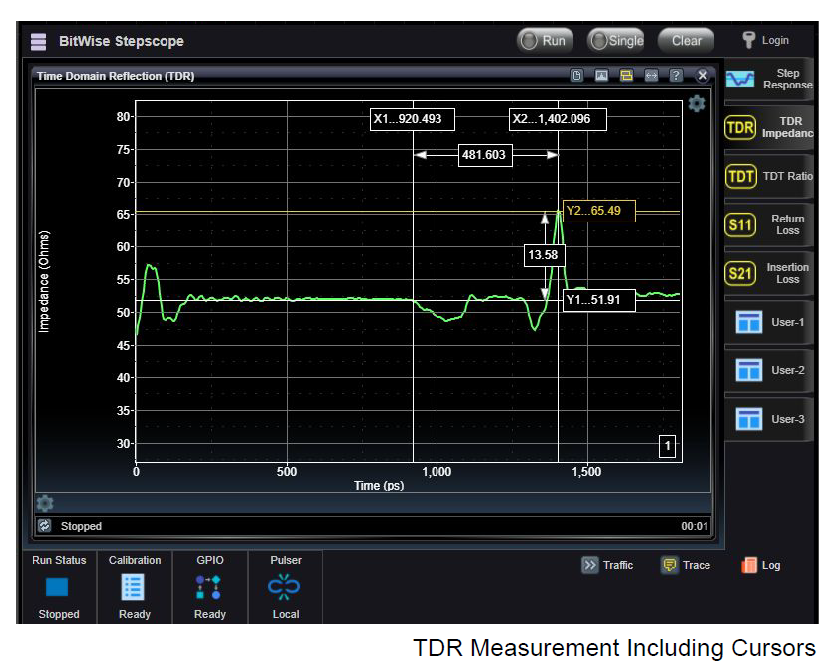
TDR shows the Impedance (Ohms) vs. Time waveform allowing users to identify impedance discontinuities resulting in inductive and capacitive impacts. The pulser’s fast edge rate allows fine details to be resolved. Waveforms can be easily downloaded as .CSV files. TDR calibration is supported to select your Reference Plane to be the end of your test cables.
-
- Single-ended or Differential
- Option Return Loss (S11) and Insertion Loss (S21) S-Parameter Measurements
- Use Two STEPScopeTM for Through-channel TDT and Insertion Loss (S21) Applications
- DC voltage outputs for Convenient Powered Component Testing
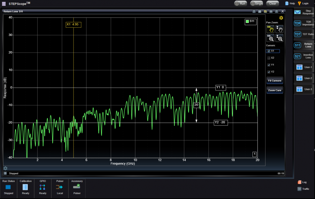
response analysis into Return Loss (S11) and Insertion Loss (S21) results. TDR, TDT, and S-Parameter analyses are proven techniques for testing RF circuits used to communicate digital information through cables, backplanes, connectors, PCB traces, wire bonding and integrated circuits. These techniques isolate impedance problems that adversely impact signal performance.
Performance
- Pulse Edge Rate : 20 psec 10/90 (typical)
- Sampler Bandwidth : 20 GHz (typical)
- Measurement Edge : Selectable Rise or Fall
- Timebase Resolution : < 100 fsec
- Pulser Rate : 4.8 ~ 78 Mhz (selectable, 16 steps)
- Pulser Amplitude : 150 ~ 250 mVpp Single-ended
- Export Format : ASCII .CSV file
- TDR I/O : 50 Ohm DC, 2.92 mm, Static Protected
- Trigger I/O : 50 Ohm AC, SMA, 2.5 GHz Sinewave
- Vdc1 and Vdc2 : +/- 5V into 50 Ohms, 50 mA Max
- Network : 10/100Mb Ethernet, RJ45
- Power Supply : 100-240 VAC to 12 V, 3A CE/FCC/UL Certified
- Power : 16 Watts (typical)
- Dimensions : 2.5” x 6” x 4”